e Tabor family of Arbitrary Waveform Generators (AWGs) allows you to define markers to be used as auxiliary outputs that are fully synchronous with the output waveforms. Two markers may be defined for each output channel.
In standard AWG models, markers are output via SMB connectors in the rear panel, as shown below.

This document will quickly guide you through the marker definition process:
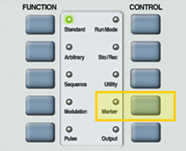
The front panel of the AWG is depicted below.
1. Press the Marker button in the control menu.

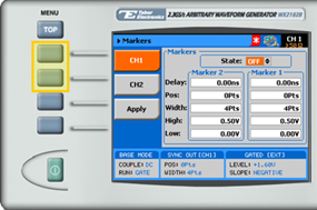
2. Select a channel to configure by pressing either the CH1 or the CH2 menu button.

3. Set the markers State to ON or OFF.
4. Configure the marker settings (in Marker 1 and Marker 2) for the channel you have selected.
- Delay. The marker delay value. The delay is measured from the waveform start position and is programmable with resolution of 10 ps, ranging from 0.00 ns to 3.00 ns.
- Pos. Sets the position of the start of the marker in reference to the waveform start point. The position is measured according to the number of samples – from 0 to the full length of the waveform, in increments of 4 samples.
- Width. The width of the marker in units of waveform points. The minimum width is 4 points and the maximum width is equal to the full wavelength of the waveform.
- High. The high level of the marker pulse, ranging from 0.5 V to 1.25 V.
- Low. The low level of the marker pulse, ranging from 0 V to 0.8 V.
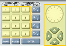
When selecting a numeric attribute for modification, modify the displayed value using the dial or the cursor keys, or by entering the value using the numeric keypad. Press ENTER to save the modified parameter value.

5. Press on the Apply menu button to update the marker memory with the modified configuration.
For More Information
To learn more about Tabor’s solutions or to schedule a demo, please contact your local Tabor representative or email your request to [email protected]