Relevant Documents
 (333KB)
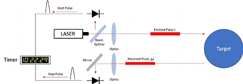
A LiDAR system consists of three main systems – the optical, electrical and processing system. A laser forms the basis for the transmitter. In some systems the laser scans the environment mechanically, by essentially moving the laser from left to right and emitting pulses of light. As with a regular radar the receiver detects the light reflected off the target, coverts it to electrical energy using a photodetector and the time delay between transmits and receive is the distance and any shift in frequency (doppler) is the velocity of the target. As light is much higher frequency than Radar the resolution of LiDAR is much better, so it is better at distinguishing between targets (10cm vs 2m at long distances 200M), giving a much more realistic representation of the environment. However, LiDAR tends to be more expensive.

LIDAR – System Overview
Typically, a laser at wavelength 905nm will pulse on for tens of ns duration and would transmit 10,000 to 150,000 times a second (10-150kHz pulse rate). Example 20ns pulse width, at a 10kHz pulse rate. The photodetector electrically translates the time and shape of the received pulse. The shape of the pulse, usually in the form of a gaussian shape, will represent the characteristics of the laser beam diffraction and target characteristics.
As previously discussed - range resolution is the ability to separate two closely spaced objects and is the main reason why you would use Lidar over Radar. New generation radars have a frequency range of 77GHz to 81GHz with a wavelength of approximately 4mm (or 4um), this gives an achievable range resolution of about 4cm (versus 75cm wavelength for legacy 24GHz radar). The wavelength of a LiDAR is about four times smaller at 905nm (or ~1um), which implies resolutions much higher than a mmWave radar can measure. However, jitter plays a larger role in LiDAR that Radar. For example, if the LiDAR system introduces 100ps jitter this will equate to 1.5cm depth uncertainty, or 300ps adds almost 5cm of uncertainty.
Innovations in LiDAR such as FMCW LiDAR and Optical Phased Array (OPA) can increase resolution and range accuracy and in the case of the OPA eliminate the mechanical parts of the LiDAR.
The challenge for the LiDAR system designer is to take this high-resolution technology to a cost and reliability point that it can be commercially deployed in mid-vehicles – which means a lot of algorithmic support and the innovative use of technologies such as AI software stacks.
Testing and Training AI algorithms
The cost of field tests is high and includes purchasing vehicles, contractors, permits and time. Making testing in Lab more financially viable, especially when testing scenarios against scenarios such as those defined in the European New Car Assessment Programme (Euro NCAP).
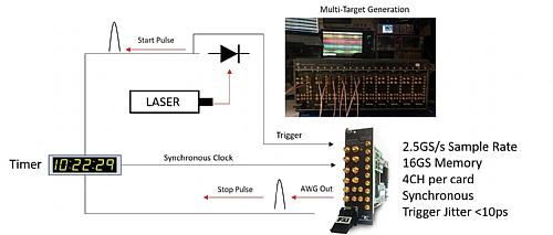
The 2.5GS/s P2584M Proteus is an ideal candidate for LiDAR scenario testing, especial for multi-target test, AI Algorithm training and compliance to standards/regulations.
A four channel Proteus P2584M for example could emulate four independent high-resolution targets pulses to test the AI algorithm – as it’s an AWG it could also emulate FMCW modulation as well. Larger memory options allowing to play out longer scenarios, with the streaming capability scenarios of infinite duration can be generated if required. A very stable triggering systems is also required, with minimal jitter.

LIDAR – Target Generation
If the AWG is not synchronized to the clock of the Lidar system (Asynchronous operation), then a typical AWG can add 440ps of jitter, as opposed to the low jitter option of the P2582/4M which is 200ps. Best operation is when the instrument and the LiDAR are synchronized (Synchronous) – and the jitter will be much less than 10ps providing excellent resolution.
For more information on Tabors Arbitrary waveform generators or to schedule a demo please contact us.