Relevant Documents
 (194KB)
Background
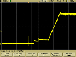
When a power supply is turned on, its purpose is to deliver, for example, 5 and 12 Volts to its “clients” – electronic components – by raising the voltage from zero to the required level. In reality, however, the voltage amplitude does not rise linearly from 0 to 5V or 12V. Instead, every power supply has its own voltage rise profile. Figure 1 illustrates a sample 0V to 5V transition as captured with an oscilloscope.

Figure 1: Non-Linear Voltage Transition
An uneven transition from 0V to 5V/12V can result in damage to connected components, or cause them to work incorrectly. In fact, every power supply has a different voltage transition profile.
As a result, manufacturers of electronic components must test their products with as many different power supplies as possible, in order to be sure that their product will work properly with their customer’s power source. This daunting process can consume a vast amount of time and human resources.
A possible solution to this problem is to simulate the behavior of the various power supplies and perform the tests automatically, with a minimum of time and effort.
Requirement
A power supply transition can be captured by an oscilloscope (as shown Figure 1 above), or supplied by the power supply manufacturer in the form of a profile. Once the transition profile is known, the Tabor Wonder Wave Series of Arbitrary Waveform Generators (AWG) can be used for the simulation and testing of various power supply transition profiles.
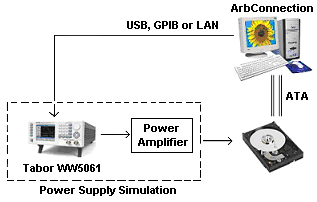
A common application for transition profile testing involves the powering-on of hard disk drives (HDDs). An appropriate test setup (see Figure 2 below) includes a computer running Tabor's ArbConnection software, and ATA testing software that triggers the AWG and monitors the HDD response. The computer is connected to the Tabor AWG, which simulates the power supply output to the HDD via a power amplifier that supplies the HDD input current. For example, a HDD that requires 5 VDC consumes approximately 2A.

Figure 2: Test Setup for Hard Disk Power On Test
The power supply voltage transition has 3 discrete segments.
- The power supply is off and its output level is 0V.
- The power supply is switched on, and the voltage output rises until it reaches 5V, where it stabilizes.
- This step starts when the voltage stabilizes, and ends when the voltage reaches a stable working condition.
The computer triggers the AWG to generate the simulated wave, and at the same time tests the HDD’s response. After a few tens of milliseconds, the power supply output stabilizes, the computer completes the HDD response test, and sends a second trigger to the AWG to complete the test. The total test duration is approximately 3 seconds.
Solution
Tabor Electronics’ Wonder Wave family of Arbitrary Waveform Generators (AWGs) serves as an excellent platform for power supply testing. Transition profiles are easily downloaded to ArbConnection – Tabor’s comprehensive software tool that controls instrument operation, and provides unsurpassed programming and waveform creation capabilities.
Wonder Wave, with its support for two output channels, can be used to test two electronic components simultaneously.
Advanced sequencing capabilities allows you to quickly create and edit complex waveforms, offering storage of 10,000 repeatable waveform segments that can be easily combined and repeated as required by the application.
Wonder Wave’s advanced memory management capabilities support highly complex applications, supporting up to 4 million memory points. It supports operation with part of the memory segments in automatic mode (advancing from segment to segment automatically), and with the other part in stepped mode (advancing from segment to segment following a trigger event). This feature is well suited for HDD testing, whereas the first and third segments are initiated by a trigger, the second segment follows the first automatically.
For More Information
To learn more about Tabor’s solutions or to schedule a demo, please contact your local Tabor representative or email your request to [email protected]